The short version
At many canal sites, water level alone cannot tell you the flow, because a downstream gate can hold the level up while less water moves. A station that also measures the water's speed fills that gap, with the Lodestar as its velocity meter. Mounted on the bed or at the surface, the Lodestar reads the water's speed at many depths at one spot in the canal, around the clock. A hydrographer, the specialist who measures flow in the field, traditionally reads one or two depths at each spot with a small spinning current meter, then moves on. Flow is the water's average speed across the channel times the area it fills, so the station also needs a separate water-level sensor and a survey of the channel's shape. The Lodestar sees only part of the channel, so the hydrographer still measures the whole flow many times, across all the canal's conditions, to build the conversion charts, called ratings, that turn the Lodestar's readings and the water level into flow. The instrument alone does not produce a flow figure.
When water level alone is not enough
The simplest continuous flow record comes from a conversion chart: record the water level, then look up the flow. Water level measured above a fixed reference level is called stage. Flow is called discharge. The chart, built from field measurements at one site, is called a rating. This stage-discharge rating works wherever the same water level always means the same flow.
Many canal sites do not behave that way. When a downstream check gate (a gate that holds the canal level up) moves, it backs water up to the site. That is backwater: the same water level, but less flow. A flume or weir submerged by high water downstream has the same problem, and some channels run backward at times. The water-level record at these sites is fine. The flow looked up from it is not, because the rating no longer holds.
Some sites add a second water-level gage and estimate flow from the slope of the water surface between the two. On a flat canal reach that slope is so small that tiny level errors become large flow errors.
A field measurement is a snapshot
Mean velocity is the water's average speed across the whole section. Multiply it by the section's water-filled area and you have the flow. No single point gives the mean velocity, so the usual way to measure flow, the velocity-area method, builds it from samples.
A hydrographer works across the channel and stops at a row of stations. At each one they measure along a vertical, the line from the water surface to the bed. They measure the depth, then the water's speed, traditionally with a current meter: a small wheel of cups or a propeller that spins faster as the water runs faster, held at one or two depths. Each vertical stands for a slice of the cross-section reaching halfway to the verticals on either side. The slice's area times the vertical's mean speed, estimated from those one or two readings, gives the water passing through it, and the slices add up to the channel's flow.
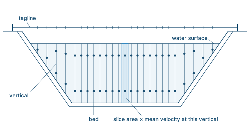
Any discharge measurement is a snapshot: it says nothing about the hours after a gate change, and a good one is accurate to about 5 percent. Today the hydrographer often makes it in minutes with a boat-mounted acoustic Doppler current profiler (ADCP), such as a HyFlow Voyager. That is a survey instrument brought to the site, not the fixed meter described below.
Measuring speed and level continuously
The index velocity method keeps the same calculation, mean velocity times area, and measures both parts continuously. It uses two ratings.
Area comes from the water level. Survey the channel's shape at a standard cross section, a marked section near the instrument that can be found and surveyed again, and every water-level reading converts to an area of flow. This chart is called the stage-area rating. Published guidance on the index velocity method calls for a re-survey every year for the first three years, then about every three years if the section is stable, and again whenever something reshapes it or later measurements stop matching the rating.
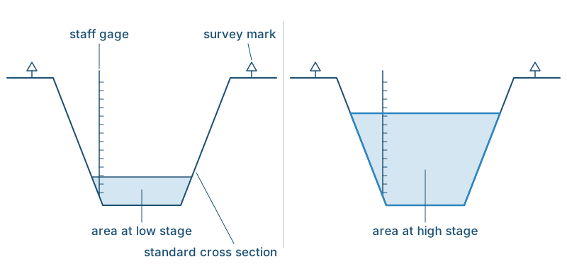
Mean velocity comes from an index. A fixed instrument measures velocity in one part of the section: the index velocity. It is like judging a highway's average speed from one lane: you must first measure how that lane compares with the whole road, and it works only while the lanes keep the same relationship. At a well-chosen site the index velocity tracks the mean velocity repeatably, and the chart relating the two is called the index-velocity rating, or index rating for short.
Because velocity is measured, not inferred from the water level, a gate change shows up in the record.
A rating is built from field measurements
The instrument does not produce a flow figure. The rating does, and a rating is built from field work.
A hydrographer makes independent discharge measurements, called calibration measurements, while the fixed instrument records index velocity and a separate water-level sensor records the water level. Each one is made nearby, with no turnout (a delivery outlet) or inflow in between.
Each calibration measurement gives one pair of numbers: what the fixed instrument read during the measurement (the index velocity, averaged over its span) and what the water's average speed actually was (the measured discharge divided by the area the stage-area rating gives for that water level). Plotted, each pair is one dot, and the line fitted through the dots is the index rating. So the stage-area rating comes first: every dot needs it.
The dots have to cover the full range of flow the site sees: low deliveries, peak deliveries, backwater from gate operations, and reverse flow where it occurs. They must cover seasonal changes too, so building a rating takes visits spread across the season. Published guidance asks for at least 10 calibration measurements for each input the rating uses (so at least 20 if it also uses the water level) and warns against stretching a rating to speeds more than twice the fastest one measured. Forward and reverse flow may plot on separate lines, each needing its own measurements.
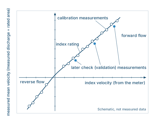
Later discharge measurements of the same kind, called check measurements (or validation measurements), then show whether the rating still holds. A shifted mount, a replaced instrument, a relined channel or heavy weed growth are reasons to measure again, and a replacement meter with a different frequency or measurement volume needs a new rating altogether. This program is normally designed and run by the irrigation district's gaging consultant, the flow-measurement specialist or firm whose hydrographers make these measurements.
Where the Lodestar fits
The Lodestar is HyFlow's fixed-site acoustic Doppler velocity meter (ADVM) for index-velocity work. It sends sound along a single narrow beam, 1.4 degrees wide, at 1.7 MHz, far above human hearing.
A siren sounds higher-pitched coming toward you than going away: the Doppler shift. The Lodestar's sound echoes off particles carried in the water, called scatterers. The shift in those echoes tells how fast the particles are moving toward or away from the instrument, and so how fast the water carrying them is moving.
The beam measures only the part of the water velocity that lies along it. A police speed gun has the same limit: it reads a car's full speed only when the car drives straight toward or away from it. From a fixed angle it reads less, a fixed share of the speed, provided cars follow the road. Likewise, with the beam at a fixed angle to the flow, the reading stays in proportion to velocity along the channel while the water runs parallel to the banks and the bed.
Echoes from farther along the beam return later, so echo timing divides the beam into a line of measurement cells, as small as 0.025 m (about 1 in). The acoustic profiling range is 0.05 to 20 m (about 2 in to 66 ft), measured along the beam.
The index velocity is normally an average of selected cells, which together make up the measurement volume, the water the index samples. The Lodestar reports every cell, with its signal strength and signal confidence. Those signals screen out bad cells, and the first calibration measurements show which cells track the mean velocity best. From then on, the way the cells are chosen stays fixed, because a different choice gives a different index from the one the rating was built on.
Which choice fits depends on the mounting your installer and consultant choose: on the bed looking up (Lodestar-B), at the surface looking down (Lodestar-S), or in the cylindrical Lodestar-U, which can be aimed at an angle across the channel. On a bed mount, published guidance prefers cells picked from the water-level record, so that they always cover the same part of the depth, however high the water is. The third post in this series covers which version suits a site.
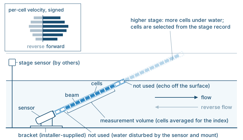
On a bed or surface mount, the beam, slanted along the channel, crosses the water column at one spot across the channel: one vertical, in the hydrographer's terms. During a discharge measurement, the current meter reads one or two depths on each vertical and then moves on. The Lodestar stays on its vertical and reads it cell by cell, from near the bed to near the surface, around the clock. The Lodestar's single-beam design was developed for this job. The index rating, built and checked from discharge measurements, does the work of the other verticals, relating that one line to the whole section.
Every cell carries a direction flag, so the index velocity is signed: plus for water moving one way along the beam and minus for the other, as on any Doppler meter. Whether reverse flow computes correctly depends on the rating.
Output is velocity over RS232 or RS485, two standard serial connections. HyFlow supplies the instrument: it does not yet sell mounting hardware or installation, and the Lodestar does not measure water level. The mount, the water-level sensor, the logger and the field measurements for the ratings come from your installer and gaging consultant.
The right site, and the right meter
No index velocity meter measures the whole section. The index rating relates the part the beam samples to the whole. That relation holds while the flow pattern across the section keeps its shape, or changes with the water level the same way every time. Published guidance says sampling representative flow (water whose speed tracks the channel's mean) matters more than sampling a large volume. The smaller the sample, though, the more it matters to place it well.
One beam measures only the part of the water's motion that runs along its line. When a gate opens or closes, it changes how fast the water moves along the channel, and that is exactly what the method measures. The trouble is motion the beam cannot sort out: water moving up and down reads as speed along the channel, more so the steeper the beam, and flow that swings off the channel's line changes the reading too. If that motion is steady, the rating absorbs it when it is built. If it comes and goes with gate settings, the rating cannot account for it, and the computed flow will be off.
So site selection comes first. Published guidance looks for a straight reach, running 5 to 10 channel widths upstream and the same downstream, or about 300 ft (90 m), whichever is longer. It asks for the same 5 to 10 widths of clearance from gates, drops, turnouts and inflows. A backwater site can often still keep that distance from its gate, because backwater can reach far up the canal: look for a straight stretch within it. Your consultant checks a candidate site first: published guidance calls for mapping its velocities from a boat, then trying a meter there temporarily.
These siting rules come first for every index velocity meter, whatever its beam count. At the sites the method is built for, a straight canal reach where backwater or reverse flow defeats a stage-discharge rating, the Lodestar is the go-to choice. It reads the water column instead of one level, works in shallow canals, has no beams to combine, can measure from the surface above the silt, and on the bed can wear a cover that sheds weed. Why the Lodestar uses one narrow beam sets out each advantage.
Unfamiliar term? See the plain-language glossary.
If you have a backwater or reverse-flow canal site where a stage-discharge rating will not hold, send us the channel shape, depth range and logger type when you Request a Quote. HyFlow can prepare a proposal for your site, drawing on our team's decades of combined deployment experience across the Asia-Pacific.